pCO2 Equilibrator Users Manual
Lamont – Doherty Earth Observatory
CO2 Group
208 Geoscience
Rt 9W Palisades, NY 10964
(845) 365-8682
csweeney@ldeo.columbia.edu
Table of Contents
Quick Start............................................................................................................................................................................................ 1
Daily Checks.......................................................................................................................................................................................... 1
Less frequent tasks........................................................................................................................................................................ 1
System Description.......................................................................................................................................................................... 1
Equilibrator..................................................................................................................................................................................... 1
pCO2 analyzer box......................................................................................................................................................................... 2
CO2 Analyzer
Box............................................................................................................................................................................... 3
Power up.............................................................................................................................................................................................. 3
CO2 standards and N2 gas
hook up..................................................................................................................................... 3
Connection of equilibrator sample line and air
sample line......................................................................... 4
Ambient Air........................................................................................................................................................................................ 4
Equilibrated air flow....................................................................................................................................................................... 4
Software Start up........................................................................................................................................................................... 4
Maintenance.......................................................................................................................................................................................... 5
Flow rates......................................................................................................................................................................................... 5
Water Manometer........................................................................................................................................................................ 5
Equilibrator flow........................................................................................................................................................................ 5
Pumps..................................................................................................................................................................................................... 6
Trouble shooting............................................................................................................................................................................. 6
No sample flow............................................................................................................................................................................... 6
No communication between computer and CO2
analyzer box........................................................................ 6
Hardware details............................................................................................................................................................................. 6
A/D modules....................................................................................................................................................................................... 6
Mass flow controller............................................................................................................................................................... 6
Solenoids............................................................................................................................................................................................. 7
Omega A/D modules...................................................................................................................................................................... 7
Appendix 1.0 The old
program................................................................................................................................................... 8
Setting up uw_pco2.ini file....................................................................................................................................................... 8
Software Start up....................................................................................................................................................................... 9
Error #24............................................................................................................................................................................................... 9
Error #62............................................................................................................................................................................................... 9
Appendix 2.0: The old
pump............................................................................................................................................................ 9
1. Plug
in CO2 analyzer power box.
-
Air pumps should not be on.
2. Turn
IR box “on”:
- Toggle
left-most switch up.
3. Check
flow for nitrogen reference gas:
-
Go to valve position 2
and turn flowmeter selection output to reference gas outlet and set for 90-100
ml/min.
4. Set
flows for standard gases:
-
Energize solenoid valve and MFC bypass (marked
“Std”) while going to valve position 4
through 10 (even # only).
-
Set flow rates ~150 ml/min.
5. Turn
on pumps and check flow:
-
Go to valve
position 1 (HOME). Equilibrator and
atmospheric air should be flowing at 45 ml/min.
6.
Set flow of
seawater to equilibrator
-
Bubbles from spray should extend at least 2 inches down from water line ~10 L/min.
7. Bring
up uwpco2.vi in C:\pco2 subdirectory.
-
Make sure that all gas concentrations and serial # match the
positions on “setup” page.
8. Check
for C:\pco2\data subdirectory in C:\pco2 subdirectory
9. Start
up program
- Press arrow in the top left-hand corner of
the screen.
1.
Flow rates of gases through IR (to mass flow meter)
-
nitrogen 60 ml/min
-
standards 60 ml/min
-
equil. & atm. 45 ml/min
2.
Water in Manometer
3.
Flow of equilibrator
4.
Make sure computer time is near GMT
5. Log
any changes to system in GMT
1. Record
offset between temperature readout and calibrated thermometer in equilibrator.
2. Send
data to csweeney@ldeo.columbia.edu (every week).
3. Check
N2 and standard tank pressures. If
standards are below 500 psi notify
csweeney@ldeo.columbia.edu
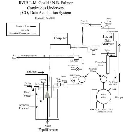
The pCO2 analysis system consists of two major
components- a seawater/air equilibrator and an automated analysis system that
uses a LI-COR infrared analyzer to measure the concentration of CO2
gas in seawater. The partial pressure of CO2 is calculated using
pressure and temperature at the time of measurement. The prototype of this system was operated on the WOCE S4P leg in
the Pacific sector of the Southern Ocean (R/V Akademik Ioffe, Feb.-Apr. 1992)
and since May 1992 has been operating continuously on the R/V Ewing, but has
not previously been described.
The equilibrator, shown
diagrammatically in figure 1, is based on the design used by Takahashi during
the GEOSECS expedition (Takahashi, 1966).
A continuous flow of seawater enters a closed equilibration chamber
through a fine nozzle, producing a fine spray, which enhances the rate of gas
exchange between water and the overlying air.
A small pump continuously re-circulates the headspace air, and a small
amount of the air (nominally 30-50 ml min-1) is diverted to the
analyzer for analysis. The air removed
for analysis is replaced by means of a "controlled leak" into the
equilibrator through a water-manometer, which allows the rate of replacement to
be monitored and which further assures that the pressure within the
equilibrator headspace cannot differ significantly from the ambient pressure in
the laboratory, which is continuously monitored. The temperature of the water in the equilibrator is measured with
a platinum resistance thermometer, which is calibrated against a high-precision
mercury thermometer traceable to N.I.S.T.
The flow of water into the equilibrator is kept great enough that the
residence time for water is less than five minutes (preferably less than two
minutes, ~ 10 L/min), while the residence time for air is approximately five
hours.
Figure
1. pCO2 equilibrator
A
second air pump draws a sample of outside air from an inlet mounted as high and
far forward as possible (to avoid contamination with stack gas) for analysis as
a sample of the ambient atmosphere.
Figure
2 shows the components of the analyzer box.
Air from the equilibrator passes through the normally-open ports of two
computer-controlled solenoid valves (plumbed in series) and subsequently
through a countercurrent flow permeation dryer prior to entering the sample
cell of the LI-COR IR analyzer (Model 6251, Lincoln, Nebraska). The output from the sample cell is directed
through a digital flowmeter, to verify the complete flushing of the cell
between analyses. If the first solenoid
valve is energized, the equilibrated air is blocked and outside air pumped from
the forward mast is directed through the dryer and IR cell. At intervals of no more than every one hour,
five calibration gas mixtures (CO2-free nitrogen and CO2 in air) are
used to determine the response of the LI-COR analyzer. The CO2-free nitrogen is also
continuously flowed through the reference side of the IR cell, and the output
of the reference side is used to flush the region of the chopper before being
used as the drying gas in the permeation dryer. In order to insure complete drying of the sample gases, the rate of the reference/drying gas flow is
kept at least twice that of the sample gases. In order to eliminate any possible excess pressure in the sample
cell, the sample gas flows are stopped for several seconds prior to reading the
CO2 signal voltage. The ambient
pressure (which equals the cell pressure with the flow stopped) is measured
using a high-precision electronic barometer (Setra Model 270, Acton,
Massachusetts) each time a sample or calibration gas is analyzed. IR cell temperature is monitored, but is not
required for the calculation of CO2 concentration.
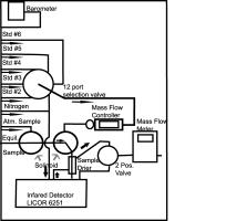
Figure 2. pCO2
analyzer box
The output of each of the sensors (IR CO2 signal and cell
temperature, barometric pressure, sample flowrate and equilibrator temperature)
is converted to a digital value using separate A/D converters (modules 1
through 5 respectively) (MetraByte, Models 1131 and 1411, Taunton,
Massachusetts). The modules are daisy-chained into the serial port of a laptop
computer. Digital outputs on two of the
A/D modules allow the computer also to control the operation of the solenoid
and stream-selection valve.
To start up, unplug air pumps until gasses are turned on and
drying incoming air. Meanwhile plug computer and pCO2 analyzer box
into appropriate power sources. There
are no separate power switches for the pumps or pCO2 analyzer box,
although the IR analyzer itself has a power switch on the lower left side,
which must be turned ON (up) AFTER the pCO2 analyzer box has been
connected to power. LED position indicator on Valco valve 12 port driver
control should be illuminated once power cable to pCO2 analyzer box
has been turned on. Digital flow
controller and meter should initially read above 200 (off scale, Figure 2), but
reading should drop to approximately 25 within a few seconds. When IR analyzer is turned on, the sound of
fan should be heard, and within a few minutes a green LED on the front of the
IR analyzer should light up, showing that the reading is stable. If pressed, each of the momentary solenoid
control switches should cause the appropriate solenoid to operate. Valco valve position selection switch will
drive valve ahead one position (STEP) or to position 1 (HOME).
Turn on the cylinders of nitrogen (valve position 2) and
calibration gases (positions 4, 6, 8, 10 and possibly 12). The nitrogen
connection has a T connection immediately upon entering the box but no flow
controller. The nitrogen port is the third bulk head fitting from the bottom on
the left side of the analyzer box (Figure 2). The consecutive positions for
each connection to the standard port increases from top to bottom (Figure 2).
There is no 5th standard for position #12.
Using the valve position selection switch and the standard
gas and mass flow control solenoid switch (button marked “std”), set the gases above the target flow rate of 60 ml/min
(between 180 and 250 if the standard mass flow controller is in line), as
indicated on the digital flowmeter, by adjusting the pressure regulators on
each cylinder. By setting the flow of the standards above the target you will
allow the mass flow controller to hold the flow at ~60 ml/min when the control
program (uwpco2.vi) has been started. Hold both switches down for about 10
seconds to get an accurate flow reading. If the mass flow controller is bypassed
using specially crimped insert all flows should be set at 60 manually.
Note
Refer to the Reference Sheet inside the cover of the pCO2 Box for
proper flow settings.
Once all calibration gas flows are set, turn flowmeter input
selection valve (marked “2 pos. valve”, also shown on Figure 2) to the
reference gas position (handle pointing up) and check that the nitrogen
reference gas flows at approximately twice that of the nitrogen (>100
ml/min). The flow of this gas is set by means of a crimp restrictor in the line
between the Tee and the filter, and can be reset only by adjusting the crimp.
This can be reset by using a vise-grip pliers and a pair of drill bits to
reduce the flow or vise-grip pliers alone, at right angles to the crimp, to
increase the flow but should only be
done under the direction of Colm Sweeney when the system is being totally
overhauled. After checking the flow
of reference gas, be sure to return the
flowmeter input selection valve to the “sample gas” position (pointing
down).
Next, set the flows of equilibrated and ambient air. (When the Standard gas solenoid is not energized, equilibrated air will
flow through the cell, unless the air solenoid is energized by pressing the
button marked “atmos” to allow ambient air to flow.) Maintaining these flows at their proper values is the key to obtaining
accurate analysis and is one of the most difficult aspects of operating the
system. Aerosol (water and/or salt) and condensate can collect in the pumps
and restrictors, causing changes in the flowrates, requiring fairly frequent
adjustment of the variable restrictions to balance the flows.
The
flow of atmospheric air is likely to have fewer problems. In order to keep the bow line well flushed
with air, the full pumping rate of the pump is utilized, with most of the flow
being subsequently discharged before reaching the IR analysis system. A Tee with a slightly restricted vent provides
the slight backpressure necessary to give a reasonable flow through the
analyzer. The flow for this is tested by pressing the atmospheric (labeled
“atmos") solenoid switch. Adjustments to this flow are made using the
needle valve inside the CO2 analyzer box (figure 2); gross
adjustments require changing the restriction to the vent downstream from the
pump. Keep the ambient air flow between 35 and 50 ml/min.
Since
this air contains fairly large amounts of aerosol, and is saturated with water
vapor at equilibrator temperature, changes in the flow are more common. In order to keep the residence time of air
in the equilibrator long, excess air cannot be vented, but must be returned to
the equilibrator. Only that portion of
the air, which passes through the analyzer, is discharged. In order to keep the pressures in the
vicinity of the pump close to ambient, simple restrictions to reduce the flow
cannot be used; instead, the pumping speed of
the new DC pump can be adjusted to control the pressure. The speed of
the pump should be opened enough so that less than ~150 ml/min of air is being
circulated to and from the equilibrator. Low flow will cut down on moisture and
aerosol build up in the sample lines.
Leaks in the circulation system will be shown
by excessive flow of replacement air into the equilibrator through the water
manometer (leak on high-pressure side of pump) or flow of equilibrated air out
through the manometer (leak on low-pressure side of pump). When the equilibrated air is flowing through
the IR cell, the replacement rate through the manometer should nearly match
that of the flowmeter; when the equilibrated air is blocked (as during
calibration periods) there should be little or no flow through the
manometer. (Excessive rolling of the
ship may cause this comparison to be difficult or impossible to make!) As
with the ambient air, the flow of equilibrated air through the IR cell should
be kept between 35 and 50 ml/min. This value is displayed on the LCD
display inside the pCO2 analyzer box as sample flows into the IR analyzer with
brief (~30 second) interruptions when actual reading are being taken by the IR
analyzer.
Connect Thermistor and GPS
The temperature probe
(Figure 1) is connected to the CO2 analyzer box by a gray data line.
This is connected to a MetraByte A/D module marked “Thermistor”.
To
start the system operating, turn on the laptop computer, check that the
computer date and time are correct (use GMT). Drive C should have the pco2
program in a subdirectory called c:\pco2. By going to that subdirectory you may
you may click on a file called uwpco2.vi. This will start up a new Labview
interface for the pCO2.
Once
the Labview VI appears you should check
to make sure that all the standard values and the bottle IDs match up. If they
are correct than you may start up the Labview VI by clicking on arrow on the
top left corner of the VI screen. Within a few seconds the 12 position Valco
valve should advance to position 2 and the standard gas solenoid should click
(signaling energizing of second solenoid in series) as the first calibration
gas flows. The program is completely
automatic from this point.
The
program is set up to log data to the ships RVDAS system through COMM port 4 and
to a file labeled YYYYDDD.RAW in the C:\pco2\data. It is possible to click on
this file while the data is being logged to check that the data is being
logged.
Once the underway CO2 system is started there is
very little that needs to be done except keep an eye on the flow rates of the
gases. The standard and nitrogen flow rates should be maintained by the mass
flow controller; however the atmospheric and seawater samples are not. Since
the equilibrator sample contains large amounts of aerosol, and is saturated
with water vapor at equilibrator temperature, changes in the flow are more
common. In addition to the flowrates, the aerosol trap (equilibrated air line)
and condensate traps (both lines) need to be checked periodically and emptied
as needed.
Flow rates:
Equil. and Atm. Samples: 35-50 ml/ min
Standards: 60 ml/min
Nitrogen 60 ml/min
It is best if the water level in the water manometer (Figure
1) is checked daily to insure that it has not evaporated. The water level on
the equilibrator side of the water manometer should not be higher than about a
1/4 inch above the upper cross tube, or else the pressure in the equilibrator
may be significantly below atmospheric pressure, and the calculated pCO2
will be too low by the same factor. One
inch of water is equivalent to almost 0.3% in pressure, or approximately 1 matm
at values close to atmospheric!
There
are relatively few adjustments that can be made on the equilibrator. A ball valve in the inlet line can be closed
partially to reduce the rate of flow of seawater, or closed completely in the
event of leaking or flooding. The nozzle is attached to a flange, which is
itself attached to the equilibrator top plate by means of four stainless steel
bolts and an O-ring seal. Remove the
bolts and carefully withdraw the entire assembly, taking care not to drop the
O-ring into the equilibrator. The
nozzle can probably be cleaned sufficiently by turning the knurled cone to
greatly increase the flow, open the ball valve with the nozzle loosely in the
hole in the equilibrator top to rinse accumulated particulate matter from the
nozzle, and readjust to give proper spray pattern. If absolutely necessary, the knurled cone can be removed by
twisting in a counter-clockwise direction with vigor.
The water drains from the equilibrator by means of gravity
flow from the overflow in the inner tower; neither the drain line
(large-diameter spiral plastic hose) nor the siphon breaker hole (in the bottom
plate of the equilibrator) should be allowed to become restricted. In the event the siphon breaker tube becomes
restricted, there is the great likelihood that water will siphon from the
equilibrator due to periodic accumulation/draining of water in the drain line
as the ship rolls. This will cause the
pressure of air in the equilibrator to fluctuate greatly, causing excessive
exchange ("breathing") between the equilibrator and the laboratory
atmosphere. This will be shown by 2-way
air exchange through the water manometer, in phase with the rolling of the
ship. No meaningful measurements can be
obtained until this situation is rectified (by reducing the restriction on the
siphon breaker, re-routing the drain line to reduce the effect of rolling, or
by reducing the flow rate of incoming water, so that the drain line can keep up
with the input.)
A second drain line, with ball valve, allows the
equilibrator to be completely emptied for servicing or cleaning. In general, this drain should not be opened
except at the end of the cruise, to prepare for removal of the system.
We have replaced a larger KNF air pump with a smaller
version of the pump which allows us to do away with the flow controlling shunt
value (see appendix). Being new it is hard for us to tell how long these pumps
are likely to last but it will definitely be necessary to change the diaphragm
head yearly. The pump for the equilibrator air can be controlled by increasing
the voltage supplied by a potentiometer (turn clockwise for an increase in pump
rate).
Trouble shooting the
CO2 analysis system is like trouble shooting any other system. Work
backwards from the symptom.
This is a common problem that results from aerosols
that will clog up the equilibrator line. To adjust flow (section 3.1, Figure 3)
start by opening up the pin valve inside the pCO2 analyzer subs box.
If this is not creating enough flow then shut down the shunt valve until the
flow rate is high enough. Do not use the back pressure valve to increase flow
because this may not allow circulation of air through the equilibrator. If non
of these procedure give enough flow, then the equilibrator air line and pin
valves should be rinsed through with DI water. Use N2 gas to
dry tubing and valves after rinsing.
In the event of loss of communication with the A/D module
stack, check all connections on the modules and related connections on the
terminal strip for breaks in continuity.
Any loss of continuity in the daisy chain will prevent communication
with all of the modules. By wiring the
serial cable directly to any one module (black to GND, red to TRANSMIT and blue
to RECEIVE), the individual module can be addressed using KERMIT (on the laptop
C: drive) (N.B.- UPPERCASE LETTERS MUST BE USED WHEN COMMUNICATING WITH THE
MODULES!). Typing "#1RS" from
the laptop should cause the module (1) to respond with its setup configuration,
as given in Table 1. See the MetraByte
manual for further information if the modules need to be reprogrammed. See also the description of the use of the
DEFAULT connection in case the modules will not communicate when connected
directly to the serial cable.
The Omega A/D modules are
located in the upper right-hand corner of the control box and allow a serial
connection to the control computer. Figure 3 shows how each module is wired to
each component. Table 1 gives the details of the use and configuration of the
modules.
The mass flow controller is a new addition
to the system (as of 9/7/01) and is
still in the testing stage. Its purpose is to regulate the flow of standards
through the IR at a flow rate of 60
ml/min. To insure that there is enough pressure to maintain the target flow
rate we recommend setting the flow rates in the fully open position at least
100 ml/min above the target to insure enough flow. To fully open the mass flow controller you need to press the
button marked “std” to fully open the mass flow controller solenoid along with
the small switch.
The solenoid bodies are constructed largely of stainless
steel, but some internal parts will rust when in contact with the salt in the
aerosol from the equilibrator. Once
this happens, the oxide will begin to interact chemically with the CO2
of the air passing through. The effect
appears to be chromatographic and reversible.
When cool, the oxide will adsorb carbon dioxide, which it will then
release when heated. Since the
“standard” solenoid is held on for approximately six minutes during the
calibration sequence, it will heat up significantly and will add CO2
to the calibration gas passing through.
When turned off at the end of the calibration sequence, the solenoid
will cool and the oxide will again adsorb CO2 from the sample gas
passing through, lowering the observed concentration in the first one or
several samples. The solenoids should
be examined for corrosion occasionally, and cleaned (or more realistically,
replaced) if a significant amount is found.
modules.
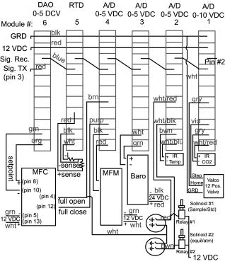
Figure 3. Configuration and wiring diagram for pCO2
A/D modules.
Table 1 (see MetraByte manual for discussion of
modules)
(all modules set for 9600 baud and
ECHO ON)
Module
# Signal Configuration (setup) Digital Output 0 Digital Output 1
1 CO2 level 310205C2
2 Cell Temp 320205C2
3 Barometer 330205C2
4 Flowmeter 340205C2
5 Equil Temp 35020DC2
6 Mass flow cntr. 36020DC2
The modules are “daisychained” together, with the
communication output (transmit) of one connected to the input (receive) of the
next in line. The computer serial port
“send data” line is connected to the input of the first module, and the serial
port “receive data” line is connected to the output of the final module in the
chain. This being the case, the
computer can “talk” directly only to the first module, and communication is
only possible with the other modules because each is programmed to echo
anything received on its input to its output (and thus to the next module in
the chain). The result of this echoing
is that any command (mostly requests for readings, or to turn digital outputs
on or off) will be sent through the entire chain and will then appear on the
input of the computer that sent the command in the first place. If the command is recognized as valid, the
addressed module will then send the requested reading (if that was the
command). Anytime the program requests
a reading from a module, the result should be the appearance of TWO strings at
the serial port input- first the echo of the command, then the reading. Anytime the program requests a change in the
state of one or more of the digital outputs, ONE string will be received by the
computer (the echo only), even though no response is required by the
program. The result is the buffer that
holds the characters received by the serial port will often contain much
unneeded information. Therefore, it is necessary to empty the buffer before
requesting a module reading, and then to “throw away” the first string received
after making the request (the echo of the command). For this reason, the program will be seen to clear the buffer (by
means of an “input” command, with the string read being ignored) before
requesting any reading (the commands to PRINT to the serial port). After requesting the reading, the program
will take TWO inputs from the serial port, with both being assigned to the same
string (q$), so that only the second input is actually used. The number of characters in the input buffer
can be checked without removal by examining the value of the variable “loc(1)”
(if the serial port was opened as #1), but anytime the data in the buffer is
read with an INPUT command, the buffer will be emptied as it is read.
Athough it should not be necessary we have equipped this
computer with the old pCO2 operating system. This system has two
main advantages over the new system. First, the executable file is only 23
Kbytes and second it does not need the support of any other program (like
Labview) to operate.
If it becomes necessary to fun the other program you first
must check the uw_pco2.ini to make sure that it has all the right settings.
This file specifies many of the operating parameters for the
operating program of the underway system. Bring DOS screen up and go into pco2
subdirectory by typing:
C:> cd pco2
<Enter>
Now type: C:> edit
uw_pco2.ini <Enter>
The file should look as shown in Figure 4.
32 , 5 , 90 , 70, 13.576 ,
.10732 , 3.110E-5
Nitrogen, 0
ca02231, 236.29
ca02235, 100.00
cc15551, 362.78
ca02205, 495.18
02-18-1999 17:38:22
Figure 4. uw_pco2.ini File display use DOS edit
Starting
with the first line: It is set for 32
samples between single runs of 5
standards. Air from the equilibrator will flow for 90 seconds and the standards will flow for 70 seconds. The double precision numbers following the sample
settings are the coefficients for the last calibration that was made and will
be updated with each set of standards. The third through the second from last
lines are the standard IDs and concentrations. The date at the bottom of the
INI file is the last time it was accessed by the NBP_PCO2.EXE program.
When finished editing press the alt key followed by the down
arrow to select quit. The edit program will prompt you to save changes.
To
start the system operating, turn on the laptop computer, check that the
computer date and time are correct (use GMT), and place a formatted empty disk
in drive A. Drive C should have the pco2 program (c:\palmeruw.exe) and the
initial file (c:\uw_pco2.ini). Start
the program by typing:
C:\pco2>
palmeruw <Enter>
Within
a few seconds the Valco valve should drive to position 2 and the standard gas
solenoid should click (signaling energizing of second solenoid in series) as
the first calibration gas flows. The
program is completely automatic from this point. The following commands will
help:
F10 To stop the program. This exit procedure
will make certain that the valves are in the proper shutdown position before
ending.
F9 To toggle switch that prints data to
floppy. Is off when program starts.
F7 To determine the amount of disk space
remaining. The high-density floppy disk
in drive A: will need to be replaced every two weeks.
F3 To toggle switch that prints data to
ships data acquisition system. Is on
when program starts.
The program gives the user the option to save each day's
data to a single disk file (F9), assigning a new name each day. There should be enough room on the disk for
roughly two weeks worth of data; to determine the amount of disk space
remaining, the F7 key from within the program. If less space remains than is
required for a single data file (approximately 70,000 bytes), end the program
(F10), replace the data disk with another high density, formatted disk and
restart the program as above.
This is a devise time out error indicating that there was no
response when the data was sent out to the data acquisition system on board. If
this was to a printer it might indicate that there was something wrong with the
printer.
This
is a end-of-file error that may show up when you first run the program. A
miss-match between the specified number of standards and number of standards
listed in the uw_pco2.ini file.
We have replaced a larger KNF air pump with a smaller
version of the pump which allows us to do away with the flow controlling shunt
value. However to be on the safe side we have a larger pump available in case
the other pumps should have problems.
The main difference between the smaller and larger pump is
the amount of air that they can pump. The old KNF (UN05) has a constant pumping
rate which pumps about 4 L of air a minute while the smaller air pump has a
pumping rate that can be regulated down to about 200 mL min-1. To control the pumping rate of the large
pump a shunt system was used (Figure 5). By opening the shunt, the flow rate to
and from the equilibrator can be regulated without significant pressure build
up at the pump. Adjust the shunt so that around 100 bubbles per minute are
being formed below the water line in equilibrator (~150 ml min-1).
Once set shunt has been set it is rarely necessary to change it again during a
cruise.
Figure 5. Equilibrator
air circulation pump.