Broadband Sparse-Array Beamforming
Beamforming
Beamforming techniques are commonly used in array signal processing to find the ray-path-arrival directions. In general, beamforming is a spatial filtering process intended to highlight the propagation direction(s) of array-recorded signals. Conventional beamforming techniques may not work when the receiving array is sparse (the receiving-array elements are many wavelengths apart).
Consider a simple broadband signal propagating through a range-independent ideal sound channel with a uniform sound speed of 1500 m/s having a flat surface and bottom (see the figure below).
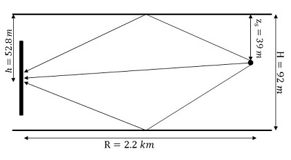 Figure 1: Ideal sound channel that supports three propagation paths. The receiving array has 16 transducers spaced
3.75 meters apart (almost 40 wavelengths at the signal's center frequency).
Figure 1: Ideal sound channel that supports three propagation paths. The receiving array has 16 transducers spaced
3.75 meters apart (almost 40 wavelengths at the signal's center frequency).
Figure 1: Ideal sound channel that supports three propagation paths. The receiving array has 16 transducers spaced
3.75 meters apart (almost 40 wavelengths at the signal's center frequency).
Figure 2 shows the plane-wave beamforming result for a broadband signal from very low frequency (10 Hz) up to 20 kHz. It shows that the plane-wave beamforming output does not have sufficient resolution at very low frequency. At 1.5 kHz, the beamforming output has enough resolution to resolve the three paths. However, there are a few side lobes. At very high frequency like 15 kHz, the array is too sparse and the plane-wave beamforming is confused. So, an unconventional beamforming technique should be developed to isolate the arrival paths when the receiving array is sparse.
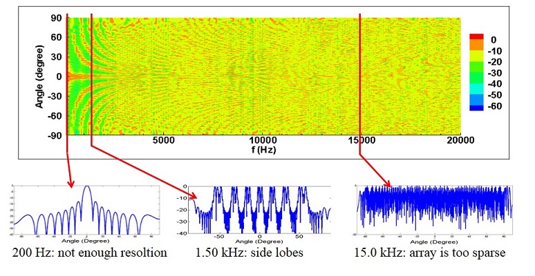 Figure 2: Plane-wave beamforming result as a function of frequency for a broadband signal (10 Hz-20 kHz)
Figure 2: Plane-wave beamforming result as a function of frequency for a broadband signal (10 Hz-20 kHz)
If the recorded bandwidth has only the high frequency information, conventional beamforming fails and there is no way to resolve the arrival angles. I have developed a novel beamforming technique to solve this problem.
Frequency Difference Beamforming
I have developed an unconventional beamforming technique (Frequency-difference beamforming) that manufactures lower-frequency signal information from the higher-frequency broadband signal recordings. The figure below illustrates the differences between conventional plane-wave and frequency-difference beamforming of the high frequency broadband simulated signal (10-20 kHz) sent to the geometry shown in Fig. 1.
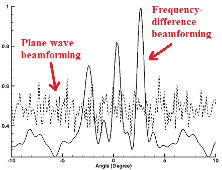 Figure 3: Magnitude of beamforming results integrated across frequency.
Figure 3: Magnitude of beamforming results integrated across frequency.