Instrument Lab
Lamont-Doherty Earth Observatory of Columbia University
61 Route 9W
Palisades, NY 10964
|
Subject: |
POS/MV-320 installation on R/V Ewing |
|
Project: |
Multibeam upgrade |
|
Created: |
April 6, 2001 |
|
Updated: |
XXX 0, 0000 |
|
Eng.: |
D. Chayes |
|
Doc No.: |
|
|
Revision: |
A |
A POS/MV-320 high quality vertical, heading and position reference unit has been purchased for the R/V Maurice Ewing. It will be installed in Panama starting on May 19th 2001 in parallel with the upgrade of the Hydrosweep.
There are three physical pieces:
- the electronics,
- the Inertial Measurement Unit (IMU), and
- the GPS reference antennas w/ choke-ring multi-path suppressors.
1 Installation details:
1.1 Antennas:
The GPS antennas will be installed on a new (to be constructed) structure on A-deck forward of the stack on A-deck. A set of the current-version drawings for this structure is attached.
1.1.1 Antenna structure:
A very rigid structure is currently being designed for installation on A-deck forward of the stack.
1.1.1.1 Issues:
Easy removal: drill and tap the doubler plates and put flanges on the bottoms of the legs?
1.2 IMU mount:
The IMU will be mounted near the center of the ship. At present, several locations are under discussion:
- in the Instrument Room near the transducer well;
- in the new Deck Department on D-deck
- in the new Science locker in the Tape Stores area
- in the vicinity of the gravity meter and gyrocompass in Tape Stores
The rigidness of the IMU mount is critical.
1.3 Cable runs and connections:
The antenna cables come down from the mast to the electronics in the Instrument Room. The IMU cables come from the IMU (most likely on D-deck or in Tape Stores, through the existing transit near the Calcomp Plotters) and to the instrument.
1.3.1 IMU cable:
The IMU cable carries power and RS-422 bi-directional data. The length limit is 100 meters.
Need diameter info from POS/MV docs.
Need connector info from POS/MV docs.
1.3.2 Analog attitude
Attitude data (pitch, roll and heave) will be interfaced to the upgraded Hydrosweep DS-2 via an analog output module in the POS/MV. The provided cable will be 3 meters long:
Need wiring details from Atlas for DS-2 end
Need wiring details from TSS for POS/MV end from POS/MV docs.
1.3.3 Network connection
The POS/MV-320 is capable of providing all of it’s data over an Ethernet connection.
Cable run and switch connection?
Define IP address (multiple?)
Need protocol details from POS/MV docs.
Need connection (10 or 100BT) connection details from POS/MV docs.
Need data volume details?
Need data format details from POS/MV docs.
1.3.4 PC (serial)
A serial (RS-232) interface is used to configure the POS/MV but is not used routinely. Custom PC software is provided for this.
Need to identify which computer will be used for this.
Define cable run(s).
Define connectors.
1.3.5 Position
The POS/MV is capable of emitting position records.
Connection to the Spectra: what format?
Connection to the HS DS-2?
Connection to the Ewing logging system?
Connection to the Instar?
Other connections?
1.3.6 GPS antenna cables:
There are two cables (one for each antenna) that run from the antenna structure to the electronics. The exact details of the antenna cable are not yet known, but they are large diameter, very low loss, high quality coaxial cable of approximately the size of RG-213U.
The antenna cables will run down one of the legs of the structure to a 4” transit that will be installed in the deck to bring the cables into the _-deck Fan Room, starboard of the centerline.
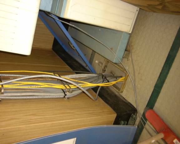
In the Fan Room, the cables will run down the side of the Machinery Control Center (MCC) to a new 4” transit in the deck and will come out in the overhead of the passage-way/ladder-well on _-deck. The cables will go through a new 4” transit in the weather bulkhead on the starboard side aft of the hatch and follow the exiting cableway forward and down to the existing transit in the deck. The cables will go through this transit in to the aft end of the man lab (Instrument Room) and forward in the overhead to the electronics that will be installed in one of the racks in the after row, facing the watch stander’s table.
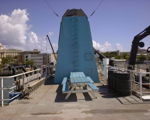
Deck foreword of the stack. The new antenna structure will be installed in the location of the tables. Attention should be paid to possible interference with the existing long-wire antennas. They may have to be moved or slightly re-located. A 4” transit will be installed in the deck near the starboard antenna leg to route the antenna cables into the Fan Room below.
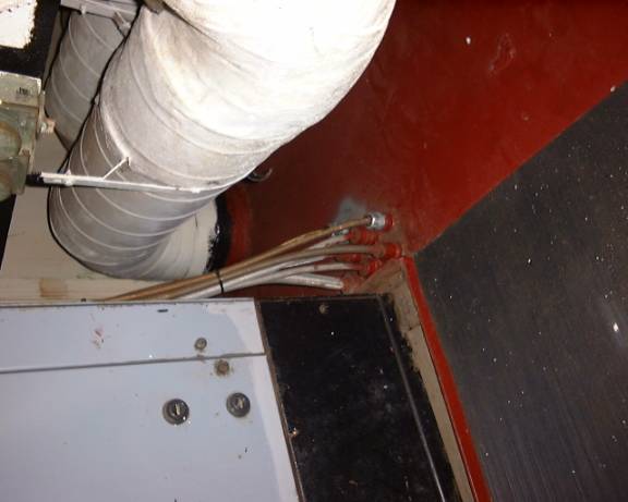
Location of a new 4” transit in the deck of the Fan Room next to the MCC. This will take the GPS antenna cables down to the overhead of B-Deck.

Location of a new 4” transit to bring the cables out to the weather deck.
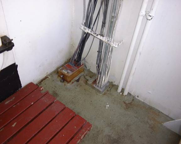
Existing transit in the B-Deck deck that will route the antenna cables into the overhead in the aft end of the Instrument Room (main lab.)
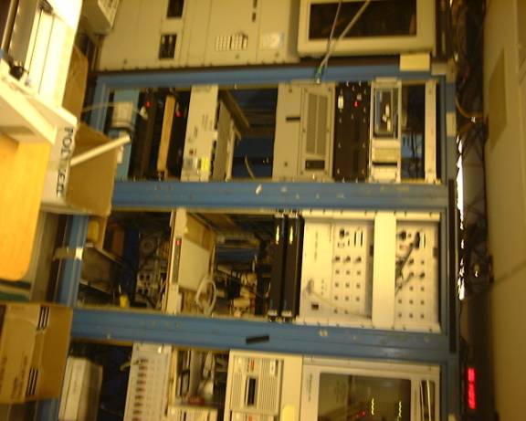
Likely rack locations for the POS/MV-320 and the new Atlas signal processor equipment.
Existing cable transit. If the IMU is installed in the D-Deck closet or in Tape Stores, the cable will pass through here.
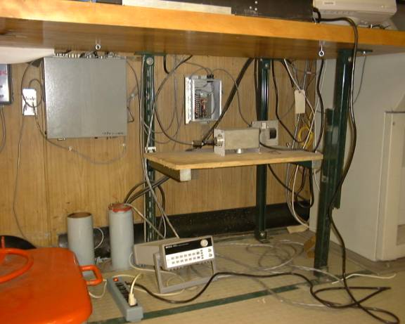
Under the existing counter aft of the HS console and forward of the transducer well hatch. It would be possible to install the IMU here.
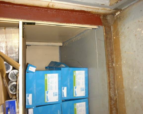
The bottom of the new shelves in Tape Stores. The IMU might go here.
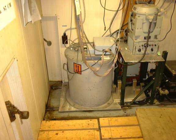
The current (April 6, 2001) HIPPY-120 vertical reference, Sperry MK-37 Mod 1 gyrocompass and BGM-3 gravity meter arrangement. There really is no space on the deck that would be suitable for the IMU. If the power supply on the bulkhead below the gyrocompass were moved, the IMU might be installed on the deck under the gyro.