Construction of the exhibit in pictures
Early experiments
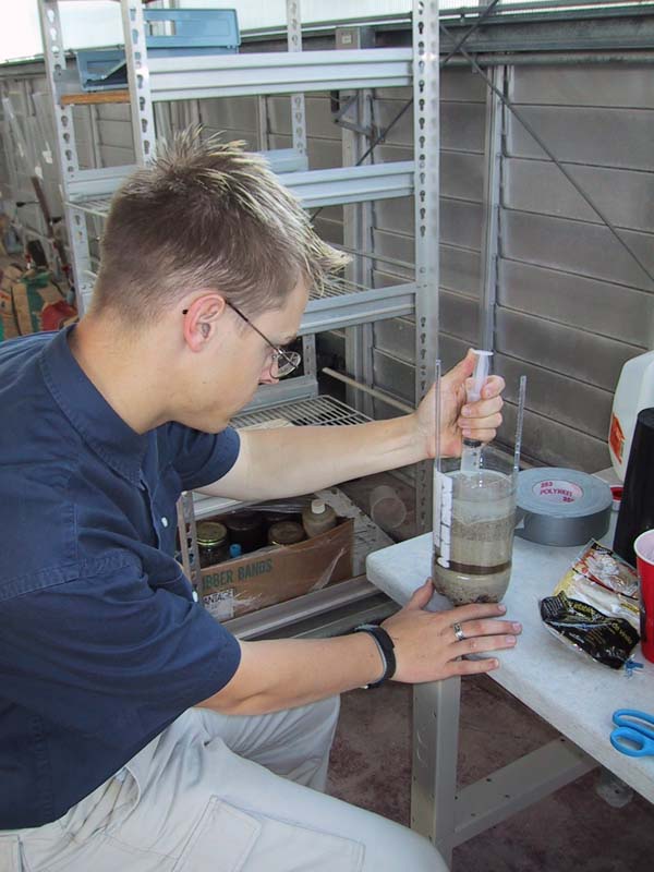
- Image: Initially we performed many
experiments on small prototypes made out of coke bottles and such to
work out all the technical details. This image shows Andrew Borden, an
Earth Semester student who helped tremendously in the early phases of
the project.
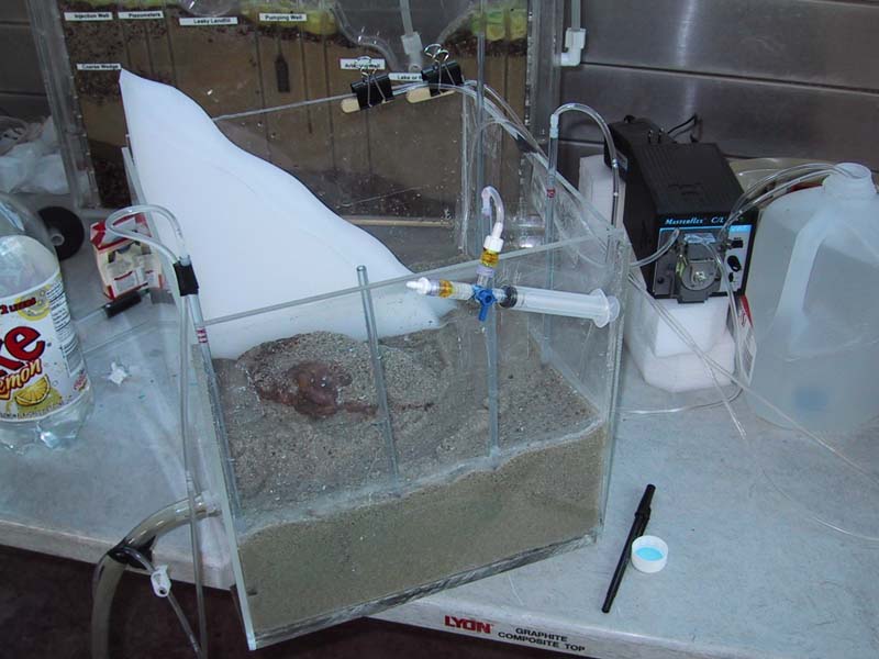
- Image: Our second prototype consisted
of a self built sand filled plexi glass box, which allowed us to test
the wells, the sandpacking and various other construction elements.
Main construction phase
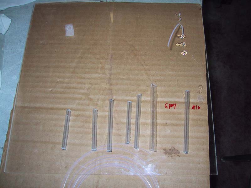
- Image:
We used acrylic plastic tubes cut at an angle at the bottom as
observation wells. We created screens by gluing a fine plastic mesh
over the end and drilled out the otehr end to insert a small barbed
fitting.
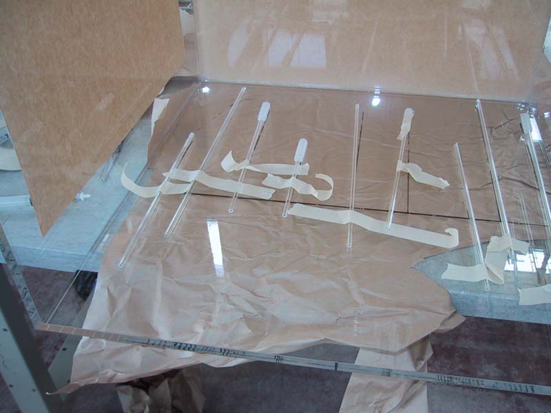
- Image:
The pumping wells were equipped with a larger diameter screen with
holes all around covered with the same mesh.
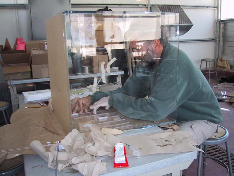
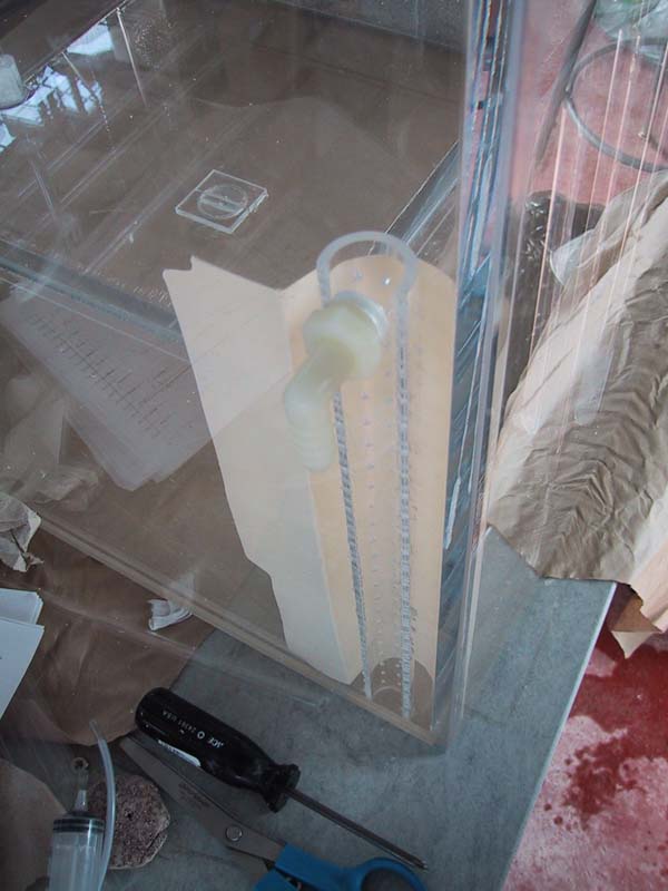
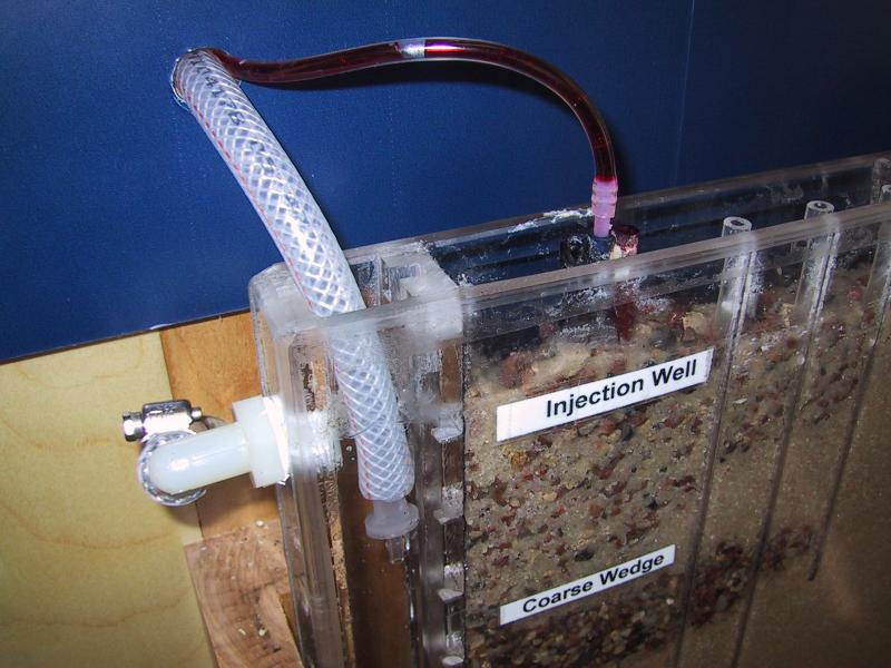
- Image: The wells were then attached to
the inside of the sand tank box.
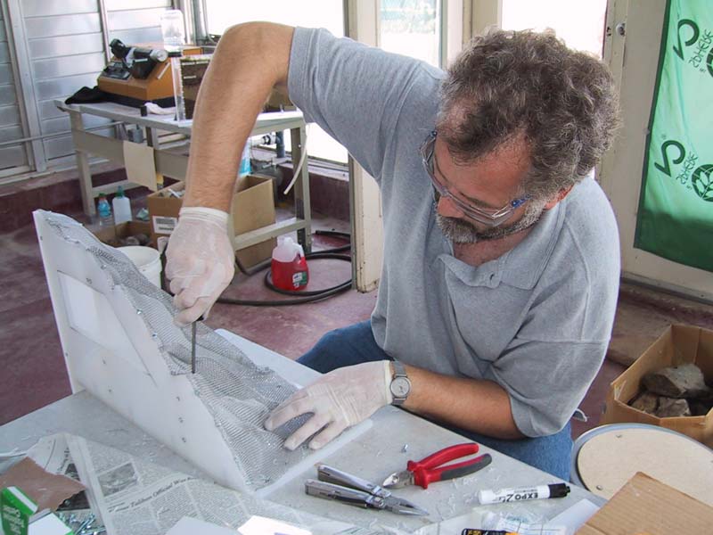
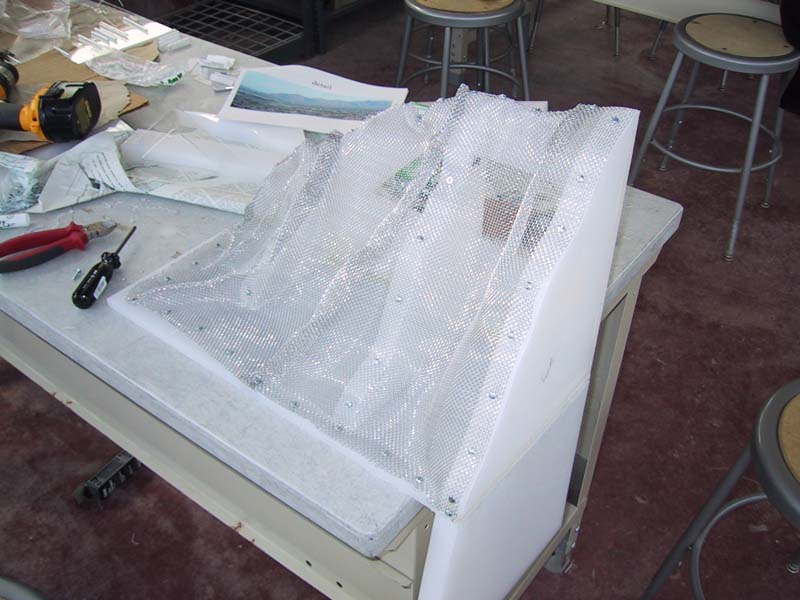
- Image: Mountains were constructed
from PVC sheet and aluminum wiremesh.
- Image: The mesh was attached with
metal scres to the PVC.
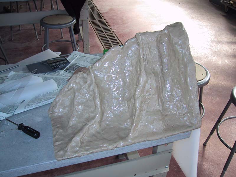
- Image: The mountains were then
formed using an epoxy putty.
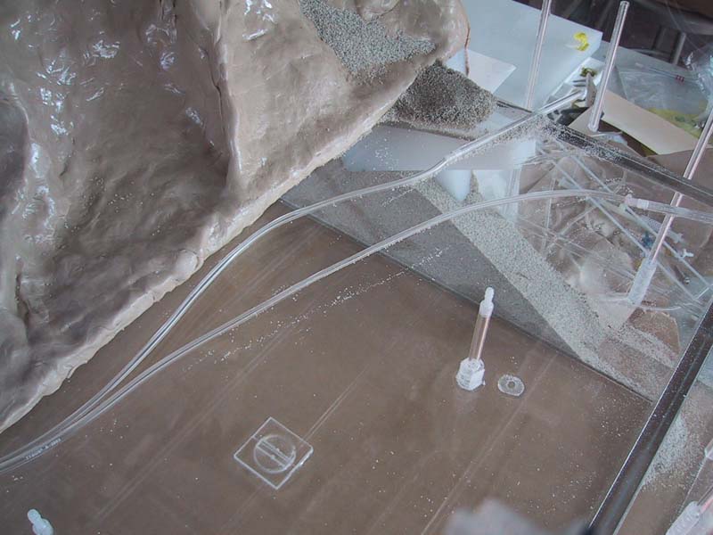
- Image: Springs in the mountains were
created by drilling small holes into the mountain and attaching tubing
to barbed fittings inserted into the holes.
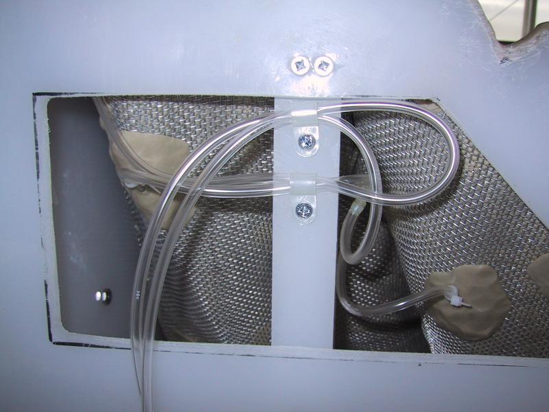
- Image: The next step was the installation
of the drain in the front left corner.
- Image: We drilled a hole for an NPT -
barbed hose fitting and added a screen with a gavel filter behind it.
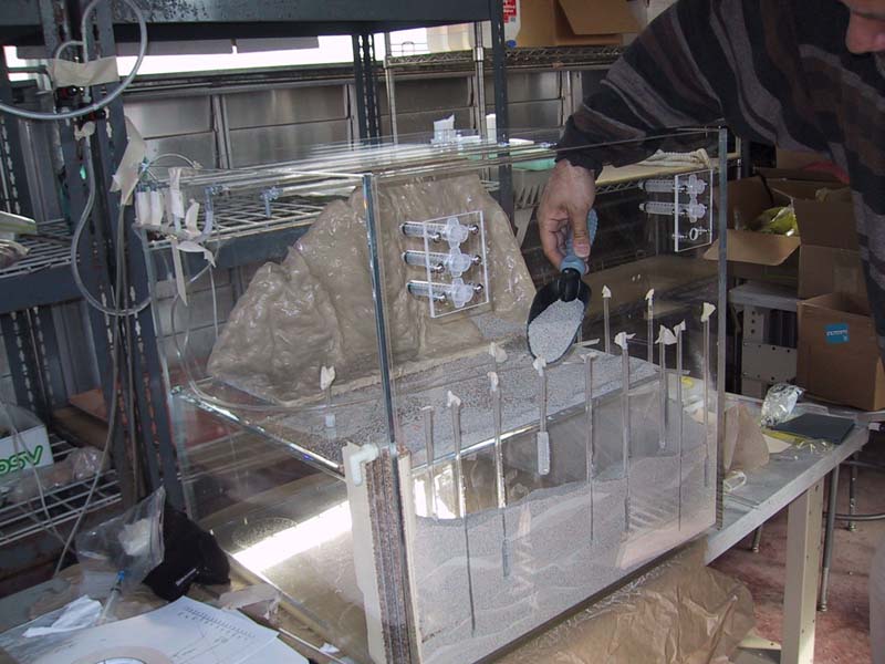
- Image: It was then time to fill the tank
with cleaned sand of various grain sizes. The inserted empty acrylic
box aloowed us to limit the amount of sand that we needed to add.
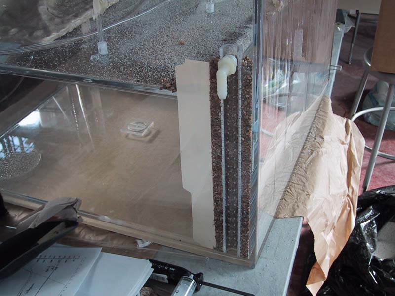
- Image: The sandfill in the lower part of
the box consists of only two ~1 inch wide columns on the left and front
side.
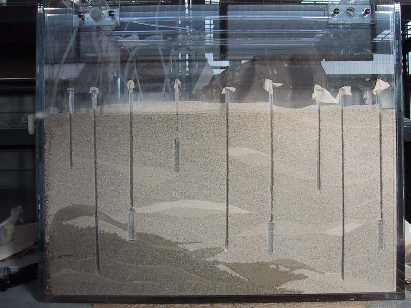
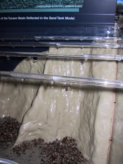
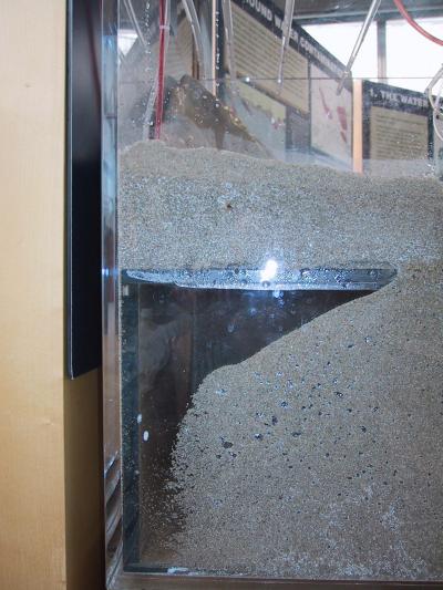
- Image: This picture shows the front of
the sand tank with the lenses created by using sand of various grain
sizes. We also began to add small quantities of degassed water to
saturate the tank from the bottom up.
- more to come
Final set-up
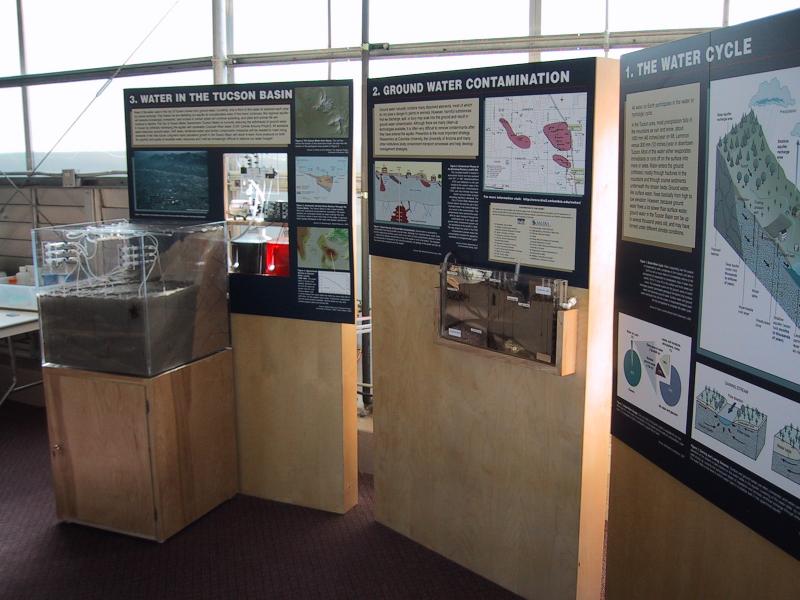
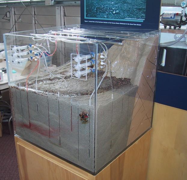
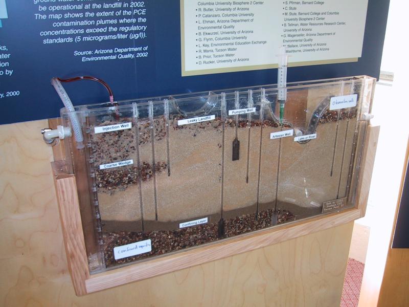
- Image: The complete exhibit
- Image: The big sand tank in context
- Image: The small tank in context
- Image: Overflow and dye injection
system for the small tank
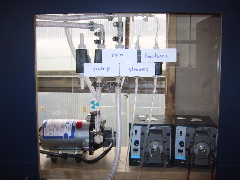
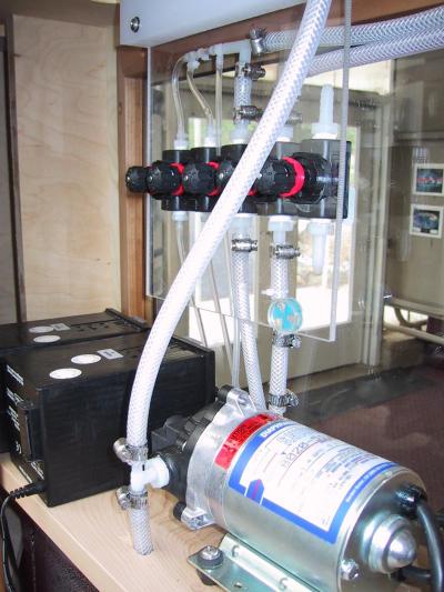
- Image: Membrane pump for pumping the
wells and peristaltic pumps for dye injection into landfill, steams and
fractures.
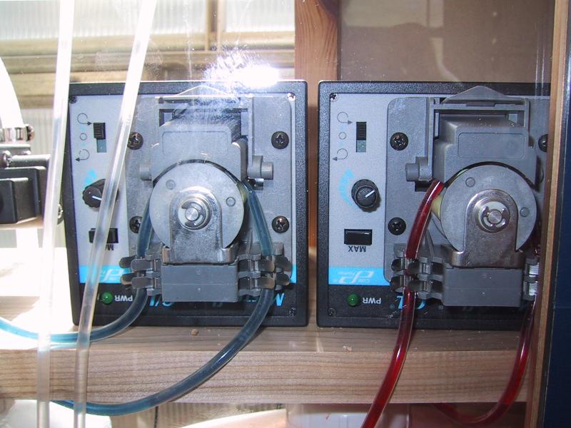
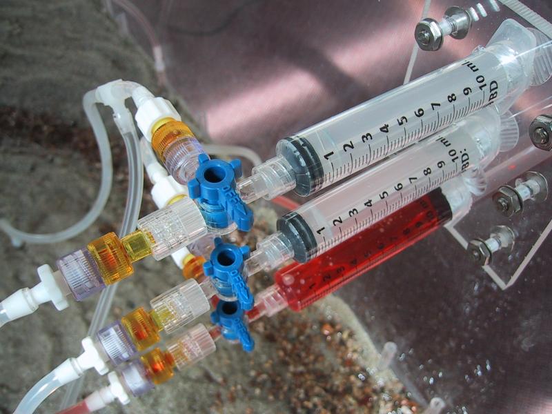
- Image: Detail of the dye injection pumps
- Image: One-gallon dye containers in the
large tank module
- Image: Pumps and valve assembly from the
back
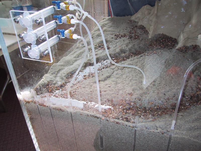
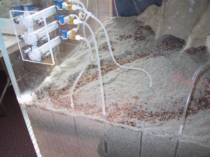
- Image: Rain distribution system
and springs in the mountains
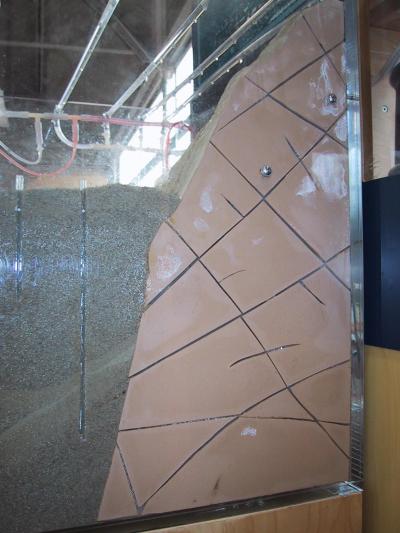
- Image: Fractures in mountains on the
side
- Image: Inner box from the left side
- Image: Syringes for manual pumping the
wells
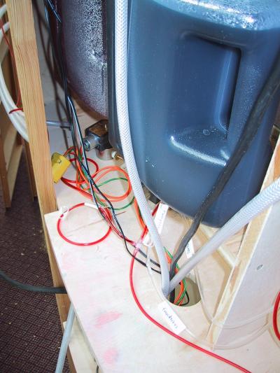
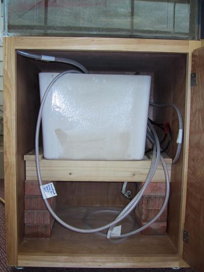
- Image: Toilet tank as reservoir for
fresh water below the big sand tank
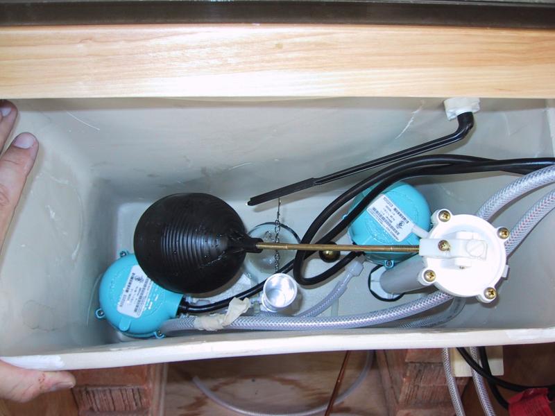
- Image: Submersible pumps for water
supply in toilet tank
- Image: Wet streams near the drain
- Image: Dry streams after pump was
turned on
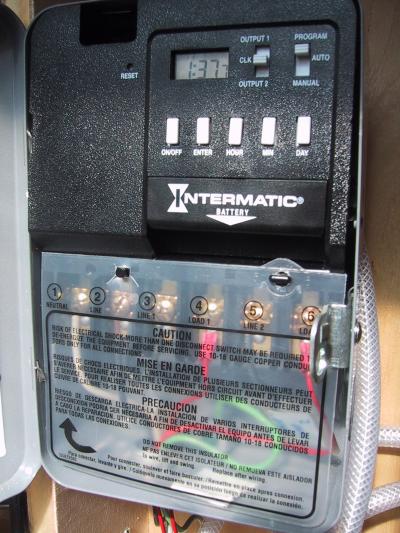
- Image: Timer for controlling dye
injection and rain events, automatic operation mode
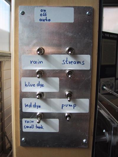
- Image: Switches for manual operation
- Image: Power distribution in large
tank module
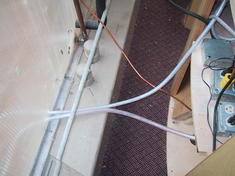
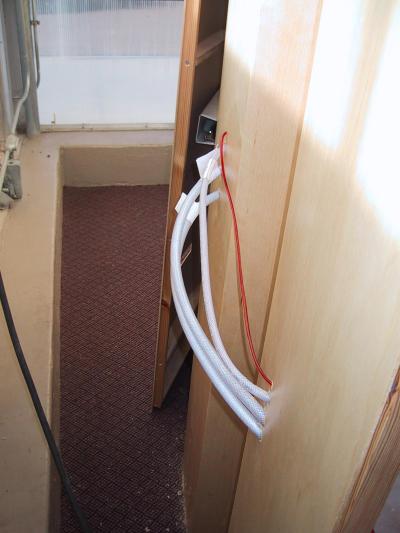
- Image: hoses connecting the modules in the
back
- Image: drain and water supply
behind the exhibit