|
 |
|
|---|
ICEPOD
An Integrated Ice Imaging System for LC-130s
Science Specifications
- STEM careers
- Pine Island Glacier
- Remote Sensing
- Measuring Ice
Lamont-Doherty Earth Observatory
EXTERNAL LINKS
Pod Science Specifications
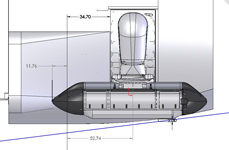
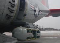
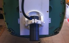
The icepod is a modular data collection and aquisition system measuring 8.5 foot long by 2 foot wide with the interior divided into three bays ~ 2 foot inside. The cones that fit onto the ends provide additional space for instruments. PDF of specifications. |
|---|
Outside |
Inside |
|
|
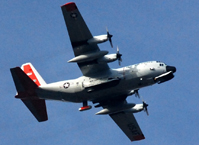
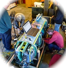
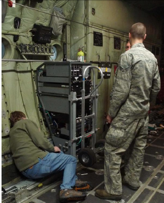
System Components: The pod is designed to be flown on a C-130 Hercules Aircraft without special modifications to the aircraft. Installation or removal can be done by in less than a day with its modular design allowing it to move to different C-130 aircraft if needed. The baseline configuration is set up for high-resolution, fine-scale temporal monitoring of ice-sheets, their margins and adjacent ocean processes. Other configurations may include atmospheric process monitoring, measurement of bathymetry in difficult to access locations, temperate climate processes, canopy definition and ‘Search and Rescue’ to name but a few. The system components include:
Platform Specification:
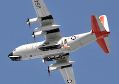 |
Hercules LC-130Cruise Altitude: 20,000ft to 28,000ft MSL
|
|---|---|
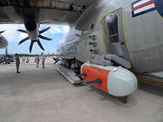 |
Icepod Door/ArmWeight: Door Plug: 120lb Unladen weight of the pod= 154lb
|
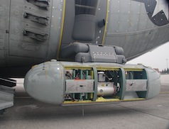 |
Icepod VolumeThe Icepod includes:
|
|
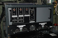
PowerIcepod system power is derived from the Aircraft Missile Support AC Bus and the Iron Lung DC Bus. It is isolated from the aircraft supply via a double conversion UPS with additional EMI Filtering. Hold-up time for the UPS is approximately 5 minutes on full load and is used to tolerate brownouts and power dropouts at ground/aircraft power handover. From Aircraft Supply: 115VAC, 400Hz Phase A from the Missile Support Bus to the Icepod SABIR Arm Drive system. Max operating power = 250W. +28Vdc from the Iron Lung Bus to the Icepod UPS. Max power demand = 1000W. Typical operational power demand = 400W. +28Vdc from the Iron Lung Bus to the Icepod dc Heater system. Max operating power = 700W. UPS Output 1: Single Phase 60Hz 115Vac to the Icepod Avionics rack UPS Output 2: +28Vdc to the Icepod sensors Icepod Sensor Power Supplies:
(Image of Avionics Rack being installed) |
Sensor Specification:
All sensor specifications, unless otherwise stated, are given for flying at the survey elevation of 3000ft AGL and survey speed of 170 knots (indicated ground-speed).
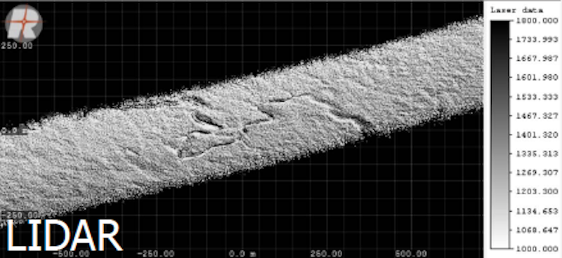 |
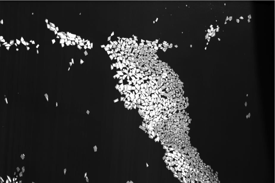
a. Lidar (Click image for data sample)Line scanner providing fully linear, unidirectional and parallel scan lines. |
|---|---|
 |
b. Depth Sounding RadarPulsed chirp depth sounding radar providing ice depth, sub-surface water distribution, internal structure. |
 |
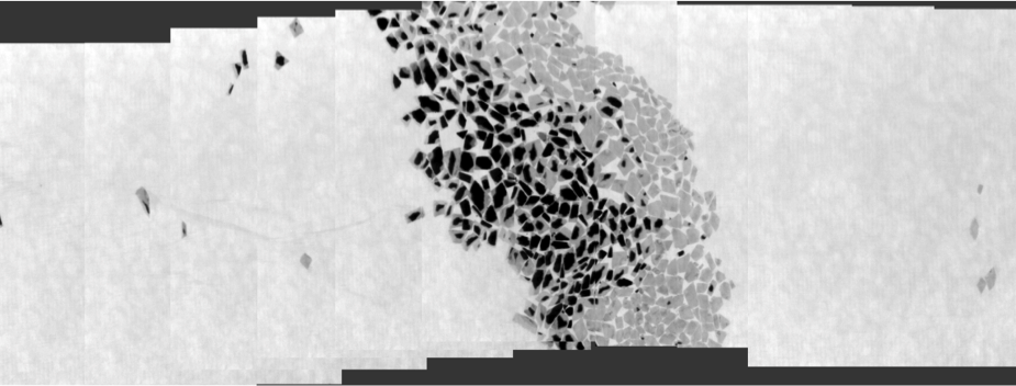
c. Visible Wave Camera (Click image for data sample)High-resolution visible wave color camera providing high quality imagery for photogrammetry and feature recognition. |
 |
d. Thermal Infra-Red Camera (Click images for data sample)High Performance thermal Infra-red, closed cycle Sterling Engine cooled camera providing high quality thermal imagery. |
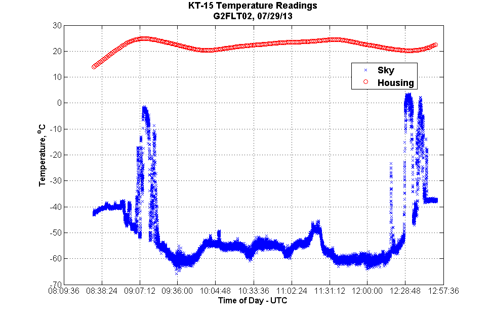 |
e. Infrared Radiation Pyrometer (Click image for data sample) The Pyrometer records sky temperature which is subtracted from the IR Camera data in post-processing to give absolute temperature of thermal imagery. |
 |
f. GNSSHigh resolution platform position and orientation. The GNSS system consists of a Novatel Span SE L1/L2 GPS Receiver and Litton based LN200 IMU mounted within the Pod. The IMU is hard mounted to the LIDAR inside the Optics bay. A Leica GNSS Receiver mounted in the Avionics rack inside the aircraft records data from a GNSS Antenna mounted on the cockpit emergency escape hatch. |
 |
g. Shallow Ice Sounding Radar (Click image for data sample)High Frequency FMCW radar that can record near-surface processes, Firn depth, Snow-pack depth, Sea-ice depth. |
Additional/Future Sensors:
 |
a. Magnetometer A Cesium-3 Total Field Magnetometer will be deployed and tested with the Icepod during the spring of 2014. Scintrex CS-3 cesium vapor magnetometer/Billingsley TFM100G2 magnetometer. Data products Magnetic anomaly (nT) Precision 0.1 nT Sample rate 100 Hz Weight 1.8 kg |
|---|---|
 |
b. Gravimeter A rack-mounted BGM-3 type Gravimeter will be tested with the Icepod system in the fall of 2014. BGM3/L&R S-80 Data products Free air gravity anomaly (mGal)/Bouguer gravity anomaly (with lidar/radar) Accuracy ~2 mGal Along-track resolution 14 km (assuming 170 s filter) Sample rate 1 Hz |
| c. CTD Sounders An AXCTD deployment system integrated into the Icepod Door Plug will be tested in the summer of 2014. One of its uses will be to measure conductivity, temperature and depth profiles close to the calving fronts of marine terminating glaciers. |
|
| d. Atmospheric Sensors A carbon dioxide sensor will be integrated into the nose cone of the pod in the summer of 2014 to test quality of airflow below the aircraft. |
Data Acquisition System Specification:
General
The Data Acquisition System consists of rugged, data acquisition computers, one for each sensor and a Master Controller or User Interface computer. The sensor computer OS can be either Linux or Windows allowing for specific manufacturer requirements. Configuration commands and data are passed between sensor computer and sensor via GigEthernet and can be converted to USB or Serial commands locally inside the pod if required. The Master Controller connects to each sensor computer via a network switch passing on User commands and taking, formatting and displaying real-time sensor data. The sensor data is time-stamped during data collection and is stored on removable solid-state hard-drives which can be removed at the end of a flight for archiving and post-processing purposes.
Display
The display shows real-time sensor current data file name, file size, instrument status, and processed images where possible converted on-the-fly from the sample data.
Special to type software
We can also write data acquisition software for clients, or co-code with clients, or integrate client software.
.
